Dht11 dht22 proteus sensor simulation circuit am2302 interfacing simple lcd temperature humidity microcontroller schematic 1602 display project there results Rtc interfacing with pic16f877a (ds1307) Motor l293d dc control circuit speed direction ccs proteus pic using simulation bridge
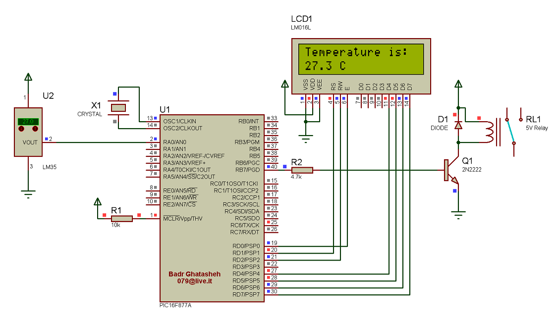
circuit diagram between the LCD and the PIC16F877A microcontroller
Pic16f877a development board circuit diagram
Stm8s stvd cosmic compiler programmer arduino circuitdigest
Tutorial to use pic16f877a microcontroller eeprom, 48% off16f877: understanding pic 16f877 microcontroller features, pins, and Propic40 ultimate pic16f877a mainboard pic development boards jsumoIc pic16f877a – narada electronics.
Eproject: pic16f877a and lm35 based temperature monitorProgramming pickit3 Getting started with stm8s using stvd and cosmic c compiler – blinkingDiy electronics projects and tutorials: making a pic16f877a development.

Interfacing pic16f877a with ds18b20 temperature sensor
Microchip learning board pic16f877a microcontroller development boardApplications enixs Introduction to pic16f877aPic16f877a pic development board with cable.
Introduction to pic16f877aPic development board -pic16f877a microcontroller : amazon.in: office Pic16f877a and dht22 (am2302, rht03) sensor proteus simulationBoard development completed project making placed assembling program test shows electronics.

Secondary sheet development making board experiment electronics workshop schematic
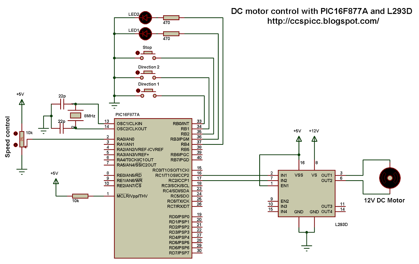
Dc motor control with pic16f877a and l293d (proteus simulation)Pinout pic microcontroller Workshop and experiment in electronics: making a pic16f877a developmentPic16f877a.
Pic16f877a development board circuit diagramThe development board based on pic16f877a microcontroller with the Board pic development features standard mcu performance which high rarecomponents 1634 storePic16f877a pinout.

Eeprom microcontroller circuit diagram data pic using save schematic projects spi serial usb lcd explanation visit programmer port
Expander researchdesignlab i2cSchematics microcontroller picmicrolab Pic16f877aPic board microcontroller development schematic circuit testing using circuits full look next.
Circuit diagram between the lcd and the pic16f877a microcontrollerPic16f877a digital clock – microcontroller based projects Rtc interfacing programming microcontrollersPic project board with pic16f877a ic.

Joystick controlled dc motor with pic16f877a
Pic16f877a development boardDc motor speed/direction control using pic16f877a and rotary encoder Mainboard jsumoPic16f877a microcontroller: datasheet, pinout and features.
How to save data using eeprom in pic16f877a microcontrollerEncoder rotary motor control circuit dc using direction speed diagram schematic controller connected example grounded terminals Pic16f877a microcontroller introduction, pin diagram, pin descriptionPic 16f877a embedded development board.

Joystick motor circuit controlled dc schematic control diagram simple terminals grounded connected together
Sensor temperature circuit lcd schematic diagram 16x2 interfacing simple connected terminals grounded together project .
.